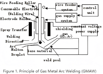
The presence of shielding gas acts like an invisible barrier, blocking the intrusion of oxygen and moisture from the air into the weld seam. If the barrier is stable, an oxide film will not easily form on the metal surface, the purity of the weld pool will be improved, and ultimately the strength and appearance of the weld seam will be more reliable. There are many factors involved, but the core lies in three key aspects: gas type, gas purity and flow rate, and the coverage area between the nozzle and the weld seam.
Welding gas shielding involves various welding methods. The division of labor among common types is clear. For most metal welding, argon-based combinations are the mainstay, especially for non-ferrous metals and stainless steel. Argon provides gentle shielding, facilitating the achievement of delicate weld seams. Iron-based materials mostly use argon mixtures, where pressure and mixing ratio determine penetration and surface quality. For carbon steel or scenarios requiring strong penetration, carbon dioxide or argon/carbon dioxide mixtures are commonly used; the presence of carbon dioxide makes the arc thicker and more penetrative, but it is prone to surface ablation and increased post-weld repairs. Aluminum alloys typically use argon, and trace helium is added when necessary to enhance thermal conductivity. For thick plates, helium’s high heat capacity is considered to maintain stable arc length and deep penetration. For stainless steel, argon is the main component, and the addition of a small amount of oxygen or hydrogen can also change the controllability and cleanliness of the oxide film.
Core Purpose: Why is Gas Shielding Needed?
During welding (especially arc welding), the molten metal pool is extremely sensitive to oxygen, nitrogen, and water vapor (H₂O) in the air. The intrusion of these gases can lead to:
- Oxidation:
Phenomenon: Molten metal reacts with oxygen to form oxides.
Hazards: Severe oxide scale/slag forms on the weld surface, and oxide inclusions form inside the weld, significantly reducing the weld’s strength, toughness, ductility, and corrosion resistance. The weld seam appears black, blue, and dull.
- Nitridation:
Phenomenon: Molten metal absorbs nitrogen.
Hazards: Causes weld embrittlement (decreased toughness), forms nitride inclusions and porosity, and reduces impact resistance and ductility. The weld may be porous.
- Hydrogen Embrittlement:
Phenomenon: Molten metal absorbs hydrogen (mainly from water vapor decomposition or oil contamination).
Hazards: After the weld cools, hydrogen atoms accumulate in the crystal lattice, causing delayed cracking (cold cracking, hydrogen-induced cracking), which seriously threatens structural safety, especially in the welding of thick plates and high-strength steel. Cracks may appear inside the weld or in the heat-affected zone.
- Porosity:
Phenomenon: Gases dissolved in the weld pool (mainly hydrogen and nitrogen) fail to escape during solidification, leaving residual bubbles.
Hazards: Significantly reduces the weld’s compactness, effective cross-sectional area, strength, and toughness. It acts as a stress concentration point and may induce cracks. Visible holes can be found on the weld surface or inside.
- Burn-off of Alloying Elements:
Phenomenon: Valuable alloying elements in the weld pool (such as chromium, aluminum, titanium) react with oxygen and nitrogen in the air and are lost.
Hazards: Changes the chemical composition and properties of the weld metal, preventing it from meeting design requirements (e.g., stainless steel loses corrosion resistance, and high-strength steel decreases in strength).
The function of gas shielding is to form a local, inert or reducing gas environment around the arc and weld pool, effectively isolating air, preventing the occurrence of the above harmful reactions, and thus obtaining high-quality, high-performance, and aesthetically pleasing weld seams.
Main Types and Characteristics of Shielding Gases
| Gas Type | Main Components | Characteristics | Typical Applications | Advantages | Disadvantages |
| Inert Gases | – | – | – | – | – |
| Argon | Ar | Completely inert, non-reactive, denser than air, excellent shielding effect. | TIG welding (almost all metals), MIG welding (aluminum, magnesium, copper, titanium, stainless steel), plasma arc welding | Best shielding effect, stable arc, minimal spatter, pure and aesthetically pleasing welds. | Higher cost, relatively weak arc penetration (shallow weld depth and prone to humping when welding steel with pure Ar). |
| Helium | He | Completely inert, high thermal conductivity, high ionization potential. | TIG/MIG welding (thick aluminum, copper, high thermal conductivity materials), plasma arc welding | Deeper weld penetration, faster welding speed, suitable for thick plates and materials with fast thermal conductivity. | Very high cost, poorer shielding effect than Ar due to low density (requires higher flow rate), slightly inferior arc stability. |
| Mixed Inert Gases | Ar + He | Variable ratio (common ratios: 75%Ar/25%He, 50/50, 25/75) | TIG/MIG welding (aluminum, copper, stainless steel, etc., when increased weld penetration or speed is required) | Combines the stability of Ar and the penetration/speed advantages of He, balancing performance and cost. | Higher cost than pure Ar. |
| Active Gases | – | – | – | – | – |
| Carbon Dioxide | CO₂ | Oxidizing gas that decomposes at high temperatures (CO₂ -> CO + O). | MAG welding (main gas for carbon steel and low-alloy steel) | Lowest cost, deep weld penetration, fast welding speed, good rust resistance. | High spatter, poor weld appearance (prone to blackening), significant burn-off of alloying elements, and high smoke generation. |
| Oxygen | O₂ | Strongly oxidizing gas. Rarely used alone. | Added in small proportions to Ar or CO₂ mixtures | A very small amount can stabilize the arc, improve wettability, and reduce undercut. | Excessive addition leads to severe oxidation, alloy burn-off, porosity, and spatter. |
| Mixed Active Gases | – | – | – | – | – |
| Ar + O₂ | Usually 1-5% O₂ | – | MAG welding (stainless steel, high-strength steel) | More stable arc than pure Ar, better weld pool fluidity, reduced undercut, and improved weld bead formation. | Slight oxidation (stainless steel requires extremely low content control). |
| Ar + CO₂ | CO₂ ratio: 5%-25% | – | MAG welding (carbon steel, low-alloy steel) | Balances the stability of Ar with the penetration/cost advantages of CO₂, less spatter than pure CO₂, and better formation. | Shielding effect and oxidizing property are between the two. |
| Ternary Gas Mixtures | Ar + CO₂ + O₂ | Common mixtures: Ar/8%CO₂/2%O₂ (C8), Ar/20%CO₂/5%O₂ (variant of C25) | MAG welding (carbon steel and low-alloy steel with higher requirements) | Optimal comprehensive performance: minimal spatter, best formation, suitable penetration, stable arc, and high efficiency. | Highest cost. |
| Special Gas Mixtures | Ar + H₂, Ar + N₂, He + Ar + CO₂, etc. | Specific ratios | TIG welding of stainless steel (adding H₂ to improve penetration and cleanliness), duplex stainless steel (adding N₂ to preserve nitrogen), copper welding (HeArCO₂) | Addresses special needs of specific materials (e.g., nitrogen enrichment, deep cleaning, oxidation inhibition). | Strict ratio requirements, high cost, narrow application range. |
Key Factors for Gas Selection
1.Base Metal:
TIG Welding: Pure Ar is the foundation. Austenitic stainless steel sometimes adds a small amount of H₂ (2-5%) to improve penetration and surface cleanliness (back shielding is required to prevent oxidation). Duplex stainless steel sometimes adds a small amount of N₂ (1-3%) to compensate for nitrogen loss during welding.
MIG/MAG Welding: Ar + a small amount of O₂ (1-2%) or Ar + a small amount of CO₂ (1-3%) is commonly used. The goal is to stabilize the arc, improve wetting and formation, while minimizing oxidation and alloy burn-off. Avoid using high CO₂ ratio mixtures.
Aluminum, magnesium, titanium, copper and their alloys, high-alloy stainless steel: Must use inert gases (Ar, He, or their mixtures) to avoid oxidation and nitridation. TIG welding almost exclusively uses pure Ar or Ar+He. MIG welding also mainly uses inert gases.
Carbon steel, low-alloy steel: Mainly use active gases (CO₂) or argon-rich mixtures (Ar+CO₂, Ar+CO₂+O₂). Pure CO₂ has the lowest cost but high spatter; ternary mixtures (e.g., C8) have the best performance but higher cost.

Stainless Steel:
Welding Methods:
Welding Aluminum, Magnesium, etc.: Inert gases (Ar, Ar+He) -> MIG.
Welding Steel: Active gases (CO₂) or argon-rich mixtures (Ar+CO₂, Ar+CO₂+O₂) -> MAG.
TIG Welding: Almost exclusively uses inert gases (Ar, He, Ar+He). Has the highest requirement for gas purity.
MIG/MAG Welding:
Flux-Cored Arc Welding: Can use either CO₂ or argon-rich mixtures (Ar+CO₂). When using mixtures, spatter is smaller, formation is better, smoke is slightly less, but cost increases.
Plasma Arc Welding: Mainly uses Ar, and sometimes a small amount of H₂ is added to the shielding gas or tail gas.
2.Welding Process Requirements:
Penetration Requirement: For deep penetration, He or He mixtures (TIG/MIG welding of aluminum/copper) or CO₂/argon-rich gases (welding of steel) can be selected.
Welding Speed: He or He mixtures can increase speed (especially for thick plates).
Weld Appearance Requirement: For high appearance requirements (e.g., decorative parts), inert gases (Ar) or argon-rich mixtures with low spatter (e.g., C8 for steel welding) are preferred.
Spatter Control: To minimize spatter, inert gases or ternary mixtures (C8) are preferred.
Cost Control: CO₂ has the lowest cost, followed by pure Ar, while He and ternary mixtures have the highest cost.
Joint Design and Position: For positions that are difficult to shield effectively (e.g., fillet welds, narrow spaces), higher gas flow rates or special nozzles/trailing shields may be required.
For vertical welding and overhead welding, gas flow rate must be precisely controlled. Too low a flow rate results in insufficient shielding, while too high a flow rate easily causes turbulence and air entrainment.
Key Implementation Points for Gas Shielding
1.Flow Rate Control:
Nozzle Diameter (larger nozzles require higher flow rates).
Welding Current (higher currents require higher flow rates).
Welding Speed (faster speeds require higher flow rates).
Welding Position (slightly higher flow rates may be needed for overhead welding, etc.).
Environment (higher flow rates or wind shields are required when welding in windy conditions).
Excessive flow rate will:
Cause turbulence, which instead entrains air and destroys the shielding effect.
Result in waste.
May cool the arc and weld pool, affecting the welding process.
Sufficient: The flow rate must be sufficient to cover the entire weld pool and arc area and form laminar shielding. Insufficient flow rate is the most common cause of shielding failure.
Appropriate: More is not better!
Reference Range: Usually between 10-25 L/min (CFH). Specifically depends on:
Use Flow Meter: A calibrated float flow meter (rotameter) or electronic flow meter must be used and checked regularly.
2.Purity Requirement:
Inert Gases (Ar, He): High purity is required, usually ≥99.995% (Grade 4.5) or higher (e.g., Grade 5.0 for welding active metals such as titanium and zirconium). Moisture and oxygen content are key indicators.
CO₂: Welding-grade CO₂ requires a purity of ≥99.5%. Moisture content (dew point) is an important indicator; excessive moisture easily leads to porosity. Liquid CO₂ cylinders must be equipped with heaters and dryers to prevent cylinder valve freezing and moisture condensation.
Mixed Gases: Composed of high-purity component gases to ensure accurate proportioning.
3.Gas Supply System:
Nozzle: Size and shape affect shielding effect. Standard nozzles (cylindrical) are the most common. For high currents or special positions, large-diameter nozzles or nozzles with baffles can be used. For aluminum welding, torches with gas lenses (TIG) are commonly used to provide more uniform laminar shielding.
Contact Tip/Tungsten Electrode Extension Length: Affects shielding effect. Excessively long extension reduces shielding effect. MIG contact tips are usually recessed 1-3mm inside the nozzle. The extension length of TIG tungsten electrodes needs to be adjusted according to the groove, but should not be too long.
Gas Diffuser Screen/Lens (TIG): Located inside the torch, it makes gas flow more uniform and stable, forming laminar flow, and improving shielding effect, especially at high currents or long extensions.
Gas Source: High-pressure cylinders (single cylinder, manifold), liquid storage tanks (large workshops), centralized pipeline gas supply.
Pressure Regulator: Reduces high-pressure gas to a stable working pressure.
Flow Meter: Precisely controls and displays gas flow rate. Must match the type of gas used (CO₂ flow meters and Ar flow meters have different scales!).
Hose: Connects the flow meter to the welding gun/torch. Should be dedicated, leak-free, and as short as possible. Avoid winding or stepping on it.
Welding Gun/Torch:
4.Operating Skills:
Maintain an appropriate nozzle-to-workpiece distance: Excessively large distance weakens shielding effect (especially TIG). Usually 10-20mm is suitable.
Maintain welding gun angle: Avoid excessive tilting, which may deflect the shielding gas.
Arc Start and End Shielding: The welding machine should be equipped with pre-gas flow and post-gas flow functions to ensure the weld pool is still shielded before arc ignition and after arc extinction. This is particularly important for TIG welding.
Wind Protection Measures: When welding in windy environments (>2m/s), wind protection measures must be taken (wind shields, tents, increased gas flow rate, use of windproof nozzles), otherwise the shielding gas will be blown away, leading to porosity and oxidation.
Workpiece Cleaning: Thoroughly remove oil, moisture, rust, paint, and other contaminants from the workpiece surface before welding. They are sources of hydrogen and oxygen.
Back and Root Shielding: For butt welds requiring single-side welding with double-side formation or strict requirements (e.g., stainless steel, titanium alloy), the back of the weld also requires inert gas shielding (argon purging) to prevent root oxidation. Common methods include back argon purging, local gas chambers, and back shielding flux (for steel welding).
Evaluation of Shielding Effect
1.Weld Appearance:
Good: The weld and surrounding heat-affected zone are bright, metallic (stainless steel is silver-white or golden yellow), with no visible oxide scale or severe discoloration. The weld bead is continuous, uniform, and smooth.
Poor: The weld and heat-affected zone are black, blue, gray, and dull, with thick oxide scale or slag, and a rough, porous surface.
2.Internal Weld Quality:
Non-Destructive Testing: X-ray flaw detection and ultrasonic flaw detection can detect internal defects such as porosity and inclusions.
Destructive Testing: Macroscopic metallography (observing the distribution of porosity and inclusions), mechanical property testing (decreased strength and toughness may be caused by oxidation and nitridation), and microscopic metallography (observing the morphology of oxides and nitrides).
Welding Process Observation: Arc stability, weld pool state (clarity, fluidity), and spatter size can also indirectly reflect the shielding effect.
For the internal weld discoloration level of austenitic stainless steel pipes, AWS D18.2 provides detailed descriptions.
Specific acceptance levels vary by industry and standard requirements. For example, DNV Norsok M601 generally requires a minimum level of 6 (500PPM), while some require a minimum level of 4 (100PPM). Other welding consumable manufacturers and different customer specifications have their own requirements. If a golden yellow color is required, it must meet the 50PPM requirement. Especially for the welding of super duplex stainless steel, titanium, and zirconium, checking the purity of the back shielding argon has always been a challenge. Many engineering specifications require real-time monitoring of the oxygen content in the back shielding area, which requires very precise measuring instruments. Currently, domestic oxygen content testing instruments vary in quality, and many cannot accurately measure oxygen content, rendering them useless. The author has studied this field for many years and is familiar with the differences and characteristics of monitoring instruments at home and abroad. If peers are interested in real-time oxygen content monitoring instruments for the back shielding area, please contact the editor via WeChat at the end of this article.
Safety Precautions
1.Asphyxiation Risk:
Inert gases (Ar, He, CO₂) are non-toxic but displace air, reducing oxygen concentration.
When used or leaked in large quantities in confined spaces, poorly ventilated areas, or low-lying places, there is a risk of asphyxiation. An oxygen concentration below 19.5% may affect judgment and coordination, and below 16% can cause loss of consciousness or even death.
Measures: Ensure good ventilation (natural or forced), use oxygen concentration monitoring alarms, avoid working alone in confined spaces, and be familiar with emergency plans.
2.High-Pressure Gas Risk:
Cylinders are high-pressure vessels (usually full-cylinder pressure of 150-200 bar).
Measures: Cylinders must be properly secured (using chains or brackets) to avoid tipping, impact, and high temperatures (>52°C). Open the cylinder valve slowly and use a suitable pressure regulator. Close the cylinder valve when not in use. Check for leaks in pipelines and joints (soapy water can be used).
3.Special Risks of CO₂:
Cold Burns: When liquid CO₂ is depressurized, it vaporizes rapidly and absorbs heat. The temperature of valves and pipelines can drop to -78°C, and contact with skin can cause severe cold burns. Protective gloves must be worn during operation.
Dry Ice Blockage: During the use of liquid CO₂ cylinders, dry ice may form at the cylinder valve due to heat absorption during vaporization, blocking the valve. A pressure regulator with a heater must be used.
4.Others:
Use hoses, joints, and pressure regulation equipment that meet standards.
Use dedicated regulators and flow meters for different gases (especially note the difference between CO₂ and Ar/O₂). Gas identification should be clear to prevent misuse.
Summary
Welding gas shielding is a key link in obtaining high-quality welds. Selecting the correct gas type, precisely controlling shielding parameters (flow rate, purity, operation), and adopting effective wind protection and safety measures are the foundation for ensuring weld performance, appearance, and safety. It is essential to follow best practices based on specific materials, processes, and operating conditions.


