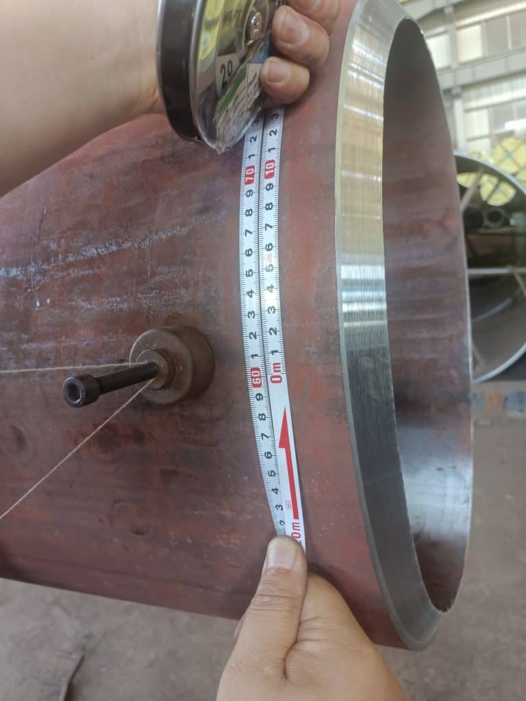
Visual inspection is a commonly used welding quality inspection method. Its main purpose is to check the surface quality of welding joints, including weld shape, dimensions, undercut, depression, porosity, etc. Visual inspection can be carried out by the naked eye or with the help of magnifying glasses, as well as auxiliary tools such as laser rangefinders and optical measuring instruments. This method can effectively detect surface defects of welding joints but cannot identify internal defects.
Overview of Core Standard Systems
Currently, global welding visual inspection mainly follows five major standard systems, each formulating detailed specifications for different materials and application scenarios.
- ISO System
Centered on ISO 5817, the latest 2023 edition covers steel/nickel/titanium and their alloys with a thickness range of 0.5-100mm, adopting three quality grades: B (Strict Class)/C (General Class)/D (Relaxed Class).
Key Revisions of the 2018 Edition
Added the crack sensitivity coefficient formula for nickel alloys: S=(Cr+3.3Mo+16N)/(Ni+0.5Mn). When S ≥1.5, the heat input needs to be adjusted.
The interpass temperature of nickel-based alloys (such as Inconel 718) is controlled below 150℃, and the porosity acceptance criteria are 20% stricter than those for steel joints.
Introduced the color judgment method for titanium alloys, requiring the dew point of the welding environment to be ≤-40℃.
The allowable misalignment of butt joints is inversely proportional to material strength. For example, S355 steel allows 0.1t misalignment, while S960 steel only allows 0.05t (t refers to plate thickness).
1.1 Key Revisions and Industry Impact Analysis of the 2023 Standard
As an authoritative international standard for welding quality assessment, ISO 5817:2023 has made several important revisions compared with the 2018 edition, with the main changes as follows:
1.1.1 Update of Key Parameter Calculation Methods
Weld penetration (s) replaces plate thickness (t): The new standard changes the calculation benchmark for allowable defect values of butt welds and fillet welds from designed throat thickness to actual throat thickness (aA). The calculation formula is adjusted to defect height h ≤0.2s/0.2aA (for Class B requirements).
Added the actual throat thickness parameter: Explicitly introduced the aA parameter in clauses 1.3/1.4/1.16/3.2 of Table 1 to strengthen the evaluation of the actual load-bearing capacity of welds.
1.1.2 Optimization of Defect Evaluation System
Schematic diagram revision: Updated 10 defect schematic diagrams, including the morphological display of defects such as lack of fusion (1.5) and undercut (1.4), making judgment more intuitive.
Acceptance standard adjustment: The allowable porosity diameter for Class B is adjusted from ≤0.5mm to ≤0.2s/0.2aA (maximum 3mm); the undercut depth requirement is changed from ≤0.05t to ≤0.1t (maximum 0.5mm).
Deleted Appendix B: Cancelled the original fatigue assessment method and replaced it with reference to the ISO 12110 series standards.
1.1.3 Strengthened Requirements for Special Materials
Titanium alloy welding: Introduced the color judgment method—silver-white is qualified, and blue/purple requires repair. The interpass temperature is controlled ≤150℃, and the heat input range is 15-45kJ/cm.
Nickel-based alloys: Retained the crack sensitivity coefficient formula S=(Cr+3.3Mo+16N)/(Ni+0.5Mn). When S≥1.5, the heat input needs to be adjusted.
The porosity acceptance criteria for γ’ phase-strengthened alloys such as Inconel 718 are 20% stricter than those for steel joints.
1.2 Comparison of Key Indicators Between Old and New Standards
| Evaluation Parameters | ISO 5817:2018 (Class B) | ISO 5817:2023 (Class B) | Change Range |
| Porosity diameter | ≤0.5mm | ≤0.2s/0.2aA (maximum 3mm) | Calculation benchmark changed |
| Undercut depth | ≤0.05t and ≤0.5mm | ≤0.1t (maximum 0.5mm) | Relaxed by 100% |
| Butt joint misalignment | ≤0.1t | Graded by material strength (0.1t for S355 steel, 0.05t for S960 steel) | Material difference considered |
| Titanium alloy acceptance | Only dimensional requirements | Added color judgment (silver-white is qualified) | New method introduced |
| Inspection benchmark | Designed throat thickness | Actual throat thickness (aA) | Core change |
1.3 Main Impacts on Industry Practice
1.3.1 Requirements for Inspection Technology Adaptation
Digital inspection systems need to upgrade algorithm modules, including: automatic measurement function of actual throat thickness (error ±0.02mm), multispectral imaging technology for titanium alloy welds (to identify color abnormalities), and correlation analysis between phased array ultrasound and weld penetration data.
1.3.2 Changes in Welding Process Control
Parameter adjustment: A car manufacturer reported that to meet the new porosity standards, the shielding gas flow needs to be increased by 15%-20%.
Case reference: In the welding of TA2 pure titanium pipes, the silver-white welds were confirmed to be free of cracks/porosity by X-ray inspection, meeting Class B requirements.
1.4 Impact on Quality Costs
Training costs: The standard conversion training requires about 16-24 class hours, mainly covering the interpretation of new defect diagrams and practical operations of weld penetration measurement (metallographic inspection process).
Inspection costs: The addition of the color judgment link for titanium alloy projects extends the single-piece inspection time by 2-3 minutes.
- AWS System
AWS D1.1:2020 targets steel structures, emphasizing practicality and flexibility in engineering evaluation, and classifies joint grades into six levels (A-F). It is a steel structure welding specification of the American Welding Society, and its weld acceptance requirements are different from ISO 5817.
- EN System
EN 1090-2/3 divides into four execution classes (EXC1-EXC4), mandating CE certification. The acceptance of aluminum structures must comply with the EN ISO 17637 visual inspection standard.
Key Updates of EN 1090-2 2025 Edition
100% UT inspection + 20% RT sampling inspection for full penetration welds.
Execution class: EXC4 class (critical structures such as ships/bridges) adds a requirement: the weld reinforcement must be mechanically processed to ±0.2mm.
Inspection conditions: Visual inspection must meet the EN ISO 17637 standard (illumination ≥500lux, inspection distance ≤600mm).
Certification process: Welders must obtain EN ISO 9606 qualifications, and automatic welders need EN ISO 14732 certification.
- GB System
GB/T 6417.1-2005 (current version) classifies defects into 6 categories, adopting the term “imperfection” instead of “defect”, which is equivalent to ISO 6520:1998.
- JIS System
JIS Z 3104 focuses on radiographic inspection of steel welds. For the general class, the angle between the X-ray and the defect is required to be <14°, and for the special class, it is <9°.
Welding Visual Defects
- Welding Visual Defects
1.1 Undercut
A groove or depression formed along the weld toe of the base metal due to improper selection of welding parameters or incorrect operation process.
Comparison of Undercut Limits
ISO 5817 Class B: Depth ≤0.05t and ≤0.5mm (t is plate thickness), defect length ≤50mm within 300mm.
AWS D1.1: ≤1mm when plate thickness <25mm; ≤2mm when plate thickness ≥25mm, 0.25mm for main pipe structures.
GB/T 3323: Prohibited for Class I, ≤0.5mm for Class II and total length ≤10% of weld length.

1.2 Surface Porosity of Welds
Porosity refers to cavities formed by bubbles in the molten pool that fail to escape during solidification. Surface porosity refers to porosity exposed on the surface.
Single porosity: Diameter ≤0.5mm (Class B standard).
Chain porosity: Multiple porosities arranged linearly.
Dense porosity: Porosities distributed in clusters.
Prevention Measures
Control the humidity of the welding environment and ensure the purity of the shielding gas.
Comparison of Porosity Limit Standards
| Parameters | ISO 5817 Class B | AWS D1.1 | EN 1090-2 (EXC3) |
| Single porosity diameter | ≤0.5mm | ≤1mm (static load) | ≤0.8mm |
| Dense porosity area | ≤1% of projection area | ≤2% of weld cross-section | ≤3 pieces per 100mm² |
| Spacing of chain porosity | ≥6 times the pore diameter | ≥4 times the pore diameter | ≥5 times the pore diameter |
| Special requirements for nickel alloys | Porosity acceptance is 20% stricter than that for steel | 100% X-ray inspection required | Helium leak detection verification required |
Porosity

Repair Methods: Grind off the section of the weld and re-weld.
Blowhole (small holes formed by gas or impurities inside or on the surface of welded components during welding)

Repair Methods:Grind off all affected welds and re-weld.
Shrinkage cavity (irregularly shaped holes with rough walls formed by shrinkage during condensation after welding)

Repair Methods:Grind off all affected welds and re-weld.
1.3 Lack of Fusion
The part where the weld bead and the base metal, or between weld beads, are not completely melted and bonded during fusion welding; the part where the base metals are not completely melted and bonded during spot welding.

1.4 Lack of Penetration
A phenomenon where the root of the joint is not completely penetrated during welding.
Causes of Lack of Penetration:
- Small welding current and shallow weld penetration.
- Unreasonable groove and gap dimensions, and excessive root face.
- Influence of magnetic bias blow.
- Excessive eccentricity of the electrode.
- Poor cleaning of the interpass and weld root.

| Parameters | Sidewall lack of fusion | Root lack of fusion | Lack of penetration |
| Typical location | Groove sidewall | Weld root | Joint root |
| Inspection method | UT angle probe inspection | RT or UT normal probe | Macroscopic metallographic section |
| AWS acceptance | Not allowed | Not allowed | Allowed under specific conditions for PJP welds |
| ISO atlas characteristics | Visible linear unbonded area on the groove surface | Unmelted root face | Weld penetration less than the designed value |
1.5 Lack of Fusion
Refers to the defect where the weld metal and the base metal, or between weld metals, are not melted and bonded together.
Root lack of fusion: The weld root is not fused with the base metal.
Sidewall lack of fusion: The weld sidewall is not fused with the base metal.


1.6 Crack
A gap formed by the destruction of the bonding force of metal atoms in local areas of the welding joint under the combined action of welding stress and other embrittlement factors, which has the characteristics of sharp notches and large aspect ratios.
| Standards | Acceptance Requirements | Special Provisions |
| ISO 5817 Class B | Any type/length is not allowed | Titanium alloy requires controlling the environment dew point ≤-40℃; 100% prohibited (including microcracks); acceptance standards for dynamic load structures are increased by 20% |
| GB/T 6417.1 | Prohibited for Class I/II welds; microcracks allowed for Class III (≤0.1t and ≤1mm) | 5x magnifying glass auxiliary confirmation required |
| JIS Z 3104 | General class: Crack length ≤3% of plate thickness; special class: ≤1% of plate thickness | Magnetic particle inspection verification required |


1.7 Incomplete Weld Fill
Continuous or intermittent grooves formed on the weld surface due to insufficient filler metal.

1.8 Weld Overlay
A metal bead formed by molten metal flowing onto the unmelted base metal outside the weld during welding. During the welding process, the local high temperature of the metal welding spot caused by electric current melts the metal, and when the liquid metal solidifies, the metal flows under its own weight to form small bumps.

Repair method: Grind off that section and re-weld.
1.9 Burn-Through
A defect where molten metal flows out from the back of the groove to form a hole during welding.

- Weld Shape Defects
2.1 Poor Weld Formation
During fusion welding, the shape of the weld formed after the condensation of liquid weld metal is called weld formation. Poor weld formation refers to the weld appearance with uneven height and width, irregular or even no weld ripples, etc.

2.2 Weld Leg Size
In the cross-section of a fillet weld, the length of the right-angle side in the largest isosceles triangle drawn. Defects are manifested as weld leg size smaller than the design requirement and uneven weld leg size (single side), etc.


2.3 Excessive Reinforcement
Reinforcement higher than required or lower than the base metal.
| Standards | Butt Welds | Fillet Welds |
| ISO 5817 | ≤(1+0.1t) and ≤5mm | Weld throat thickness deviation ±15% |
| AWS D1.1 | ≤3mm | Allowable size deficiency 2-3mm |
| EN 1090-2 | According to EXC class: ≤1.2mm for Class B | Weld leg asymmetry ≤20% |


2.4 Misalignment
A situation where the two base metals are not on the same plane during butt welding.

2.5 Missing Weld
The required weld is not welded. It is manifested as the entire weld not being welded, part of the entire weld not being welded, unfilled arc crater, and the weld not being filled or completed, etc.

2.6 Missing Installation
One or more parts in the structural component are not assembled and welded.
2.7 Spatter

2.8 Arc Strike

- Composite Defects
Two or more types of defects exist simultaneously in the same weld or the same location of the same weld.

- Weld Grinding
Requirements for weld grinding: After grinding, the weld shall meet the inspection standards, with a smooth transition between the weld and the base metal, and no damage to the base metal is allowed.

Application of Digital Atlas Inspection Technology
- Architecture of Intelligent Inspection System
Modern welding inspection systems usually adopt the following technical architecture:
Data acquisition layer: Obtain weld images through industrial cameras, laser scanners and other equipment.
Data processing layer: Use AI algorithms for defect identification and classification.
Performance indicators: Crack detection rate 99.7%, recognition speed 120FPS (Weishi Zhizao PCB inspection system); automotive body-in-white inspection: 5G transmission reduces rework rate by 80%; wheel hub welding inspection: 0.8 seconds/piece, 1125 times faster than manual inspection.
Decision-making layer: Automatically determine the weld quality grade according to preset standards.
Data management: Establish welding quality files to realize full life cycle traceability.
- Industry Application Cases
Automotive Manufacturing Field
The “Welding AI Quality Online Intelligent Inspection” system developed by Rootcloud has been applied to the welding inspection of automotive body-in-white: real-time collection of welding data and PLC data through 5G network, monitoring of welding process parameters using AI algorithms, realization of 100% welding spot inspection, establishment of welding files with vehicle ID tags, and support for quality traceability. Typical case: A car manufacturer reduced the welding rework rate by 80% after introduction.
Shipbuilding Field
An automatic hull weld defect detection method based on improved YOLOv5: Uses deep learning algorithms to identify weld defects, with high detection accuracy and speed, suitable for large-scale applications, capable of identifying tiny defects and solving the problem of missed detection in traditional inspection methods.
Standard Implementation and Inspection Suggestions
- Standard Selection Guide
Steel structure welding: Prioritize the AWS D1.1 standard.
International projects: Recommend the ISO 5817 standard.
EU CE certification projects: EN 1090-2/3, EXC3 class requires full penetration welds.
High-demand occasions: Select Class B acceptance standards.
Special materials: Nickel/titanium alloys need to refer to special clauses; ISO 5817:2023 is recommended for titanium alloy pressure vessels, with interpass temperature ≤150℃.
Automotive lightweight components: Recommend ISO 13919-1 electron beam welding.
|
Application Scenarios |
Recommended Standards | Technical Supporting Solutions |
| EU CE certification | EN 1090-2/3 | Welder EN ISO 9606 certification + digital report |
| North American steel structures | AWS D1.1:2024 | Phased array ultrasound + magnetic particle inspection combination |
| Aerospace titanium components | ISO 5817:2025 | Color judgment + quantum sensing stress analysis |
| Additive manufacturing parts | GB/T 6417.1-2025 | Industrial CT scanning + AI defect classification |
- Suggestions for Inspection Process Optimization
Pretreatment: Clean the weld surface to remove scale and spatter.
Visual inspection: Use a 5x magnifying glass for auxiliary observation (required by EN ISO 17637).
Digital inspection: Adopt AI vision systems for automatic defect identification.
Result judgment: Classify the quality grade according to the applicable standards.
Data filing: Establish electronic inspection records for easy traceability.
- Technology Development Trends
In-depth AI application: Deep learning algorithms improve the accuracy of defect identification.
Multi-sensor fusion: Combine multi-modal data such as vision, infrared, and ultrasound.
Cloud collaboration: Welding data sharing and process optimization.
Automation integration: Seamless connection with AGV, robotic arms and other equipment.
Digital twin application: Welding simulation error ±0.02mm, virtual test welding reduces physical tests by 40%.
Quantum sensing technology: Diamond NV center sensors detect micro-scale residual stress, with detection accuracy: residual stress ±5MPa, spatial resolution 10μm, 100 times higher than traditional XRD accuracy.
Summary of Welding Visual Inspection
With the progress of society, the means and methods of welding visual inspection have kept pace with the times. From 2023 to 2025, welding visual inspection technology is centered on AI vision and automated systems, combined with 3D scanning and deep learning, achieving millisecond-level inspection (such as Tesla’s 30ms/welding spot) and 99.2% accuracy; the update of ISO 5817:2024 strengthens the calculation of actual throat thickness and defect classification, and adds schematic diagrams to improve inspection consistency.