Vacuum heat treatment refers to a heat-treating process in which the workpiece is heated to the required temperature in a vacuum atmosphere of 10⁻¹~10⁻² Pa, followed by cooling in different media using different methods.
Vacuum heat treatment is recognized in the modern heat-treatment industry as an efficient, energy-saving, and pollution-free clean heat-treatment technology. Parts treated by vacuum heat treatment feature no oxidation, no decarburization, degassing, degreasing, excellent surface quality, minimal deformation, high comprehensive mechanical properties, and stable reliability. Therefore, vacuum heat treatment has gained wide attention and extensive application worldwide. The popularity of vacuum heat treatment is even regarded as an important indicator of a country’s heat-treatment technological level. Over the past forty years, vacuum heat treatment has been a major focus of heat-treatment process development and remains a critical field within today’s advanced manufacturing technologies.
Vacuum heat treatment requires extremely strict process control and systematic management of equipment, process parameters, and operating details.
Equipment and Environmental Requirements
- Vacuum system reliability
The vacuum level must reach 10⁻²~10⁻⁴ Pa (depending on material). Leakage rate must be tested regularly (≤0.67 Pa·L/s).
Weekly inspection of mechanical pump oil level/quality; quarterly cleaning of diffusion pump to prevent oil vapor contamination.
- Heating elements and insulation layers
Graphite/molybdenum heaters must be protected from metal vapor deposition (especially for copper or zinc alloys). Electrodes should be cleaned monthly.
Carbon-felt insulation must avoid contact with water/oil; otherwise, decomposition at high temperature lowers vacuum.
- Cooling system
Gas quenching pressure range 2–20 bar (adjusted to part thickness). Nitrogen purity ≥99.995% (dew point ≤ –60°C).
Oil quenching must use low-vapor-pressure vacuum quenching oil (<10⁻³ Pa at 20°C), with regular cooling-curve testing.
Key Points of Process Control
- Furnace loading specifications
Workpiece spacing ≥10 mm to avoid temperature non-uniformity; complex parts require special fixturing (e.g., molybdenum wire supports).
Loading volume ≤70% of usable chamber volume to ensure uniform gas circulation.
- Coordinated control of temperature and vacuum
| Stage | Temperature Range | Vacuum Requirement | Function |
| Low-temperature Stage | < 600°C | High Vacuum (10⁻² Pa) | Degreasing, Degassing |
| Heating-up Stage | 600°C → Target Temperature | Medium Vacuum (1 ~ 10⁻¹ Pa) | Prevent Alloy Element Evaporation |
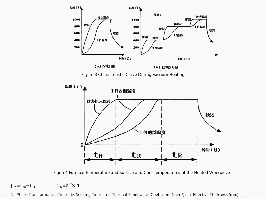
| Holding Stage | Target Temperature | Low Vacuum (10 Pa) | Ensure Uniform Temperature |
- Cooling control
Gas quenching: Large-section parts need ≥6 bar high-pressure nitrogen; thin-wall parts should use argon to reduce deformation.
Oil quenching: Oil temperature ≤80°C; oil tank must be pre-charged with nitrogen to 40 kPa to prevent explosion.
- Vacuum requirements
| Material | Required Vacuum Level During Vacuum Heat Treatment (Pa) |
| Alloy tool steel, structural steel, bearing Steel (tempering temperature below 900°C) | 1–10⁻¹ Pa |
| Alloys containing Cr, Mn, Si, etc. (heated above 1000°C) | 10 Pa (with high-purity backfilled gas) |
| Stainless steels (Precipitation-Hardening Alloy), Fe-, Ni-based alloys, cobalt-based alloys | 10⁻¹–10⁻² Pa |
| Titanium alloys | 10⁻² Pa |
| High-Speed Steel (HSS) | 1000°C backfill 666~13.3Pa N₂ |
| Cu and Cu-based alloys | 133–13.3 Pa |
| Tempering of High-Alloy Steel | 1.3–10² Pa |
- Heating and preheating temperatures
| Quenching Heating Temperature (℃) | Preheating Temperature (1) (℃) | Preheating Temperature (2) (℃) | Preheating Temperature (3) (℃) |
| 800-900 | 550-600 | – | – |
| 1000-1100 | 550-600 | 800-850 | – |
| Above 1200 | 550-600 | 800-850 | 1000-1050 |
- Vacuum quenching heating time

- Cooling methods of vacuum heat treatment
1) Gas quenching
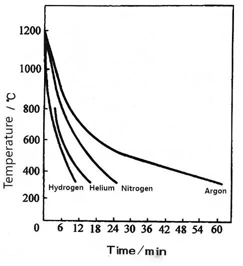
(1) Properties of various cooling gases
Table 4 Properties of Cooling Gases (at 100°C)
| Gas | Density (kg/m³) | Prandtl Number | Viscosity (kg·s/m³) | Thermal Conductivity (kcal/m·h·°C) | Relative Thermal Conductivity |
| N₂ | 0.887 | 0.70 | 2.5×10⁻⁶ | 0.0269 | 1 |
| Ar | 1.305 | 0.69 | 2.764 | 0.0177 | 0.728 |
| He | 0.172 | 0.72 | 2.31 | 0.143 | 1.366 |
| H₂ | 0.0636 | 0.69 | 1.048 | 0.189 | 1.468 |

Figure 5 Relative Cooling Capacity of Hydrogen, Helium, Nitrogen, and Argon
To ensure no oxidation and high surface brightness, nitrogen purity requirements must be satisfied.
Table 5 Nitrogen Purity Standards
| Material | Nitrogen Purity (%) |
| Bearing steel, high-speed steel | 99.995–99.998 |
| High-temperature heat-resistant alloy | 99.999 |
| Highly reactive metals | 99.9999 |
| Semiconductor materials | 99.99999 |
Table 6 Industry Standards for Argon, Hydrogen, and Nitrogen Used in Heat Treatment
| Name | Specification Requirements, % (V/V)
|
||||||
| Argon Content | Nitrogen Content | Hydrogen Content | Oxygen Content | Total Carbon Content (as Methane) | Water Content | ||
| High-Purity Argon | ≥99.999 | ≤0.0005 | ≤0.0001 | ≤0.0002 | ≤0.0002 | ≤0.004 | |
| Argon | ≥99.99 | ≤0.007 | ≤0.0005 | ≤0.001 | ≤0.001 | ≤0.002 | |
| High-Purity Nitrogen | – | ≥99.999 | ≤0.0001 | ≤0.0003 | ≤0.0003 | ≤0.0005 | |
| Pure Nitrogen | – | ≥99.996 | ≤0.0005 | ≤0.001 | CO≤0.0005
CO₂≤0.0005 CH₄≤0.0005 |
≤0.0005 | |
| Industrial Gaseous Nitrogen | I Category | – | 99.5 | – | ≤0.5 | – | Dew Point ≤ -43℃ |
| II Category (Grade I) | – | 99.5 | – | ≤0.5 | – | Free Water ≤ 100ml per I Cylinder | |
| II Category (Grade II) | – | 98.5 | – | ≤1.5 | – | Free Water ≤ 100ml per I Cylinder | |
| Hydrogen | – | ≤0.006 | ≥99.99 | ≤0.0005 | CO≤0.0005
CO₂≤0.0005 CH₄≤0.001 |
≤0.003 | |
(2) Methods to improve gas-cooling capability
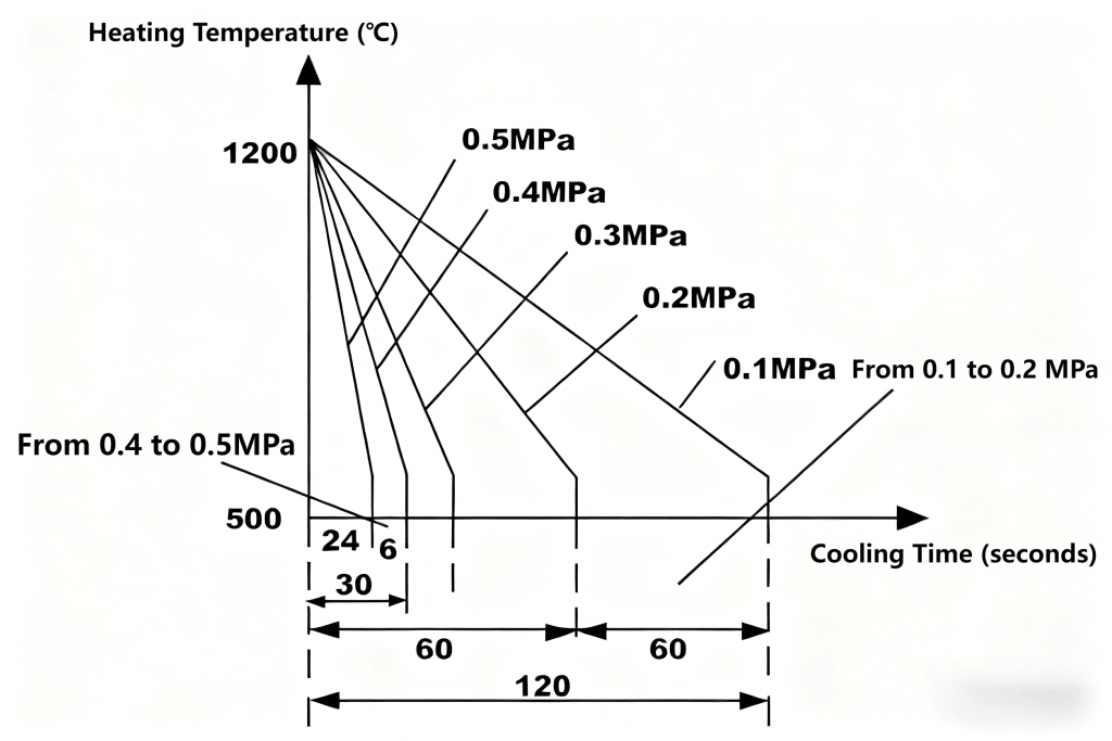
Increasing gas density (pressure) and flow velocity proportionally increases convective heat-transfer efficiency.
① Increase gas pressure
② Increase gas flow rate

Figure 6 Relationship Between Gas Pressure and Quenching Rate
Table 7 Comparison of Heat-Transfer Coefficients of Various Quenching Media
| Quenching Media and Quenching Parameters | Heat-Transfer Coefficients (W/(m²·K)) |
| Salt Bath at 550℃ | 350~450 |
| Fluidized Bed | 400~500 |
| Oil (20~80℃, Non-flowing) | 1000~1500 |
| Oil (20~80℃, Stirred Circulation) | 1800~2200 |
| Water (15~25℃) | 3000~3500 |
| Air (No Forced Circulation) | 50~80 |
| 1000 mbar (1×10⁵ Pa) N₂ Circulation | 100~150 |
| 6×10⁵ Pa N₂ Rapid Circulation | 300~400 |
| 10×10⁵ Pa N₂ Rapid Circulation | 400~500 |
| 6×10⁵ Pa He Rapid Circulation | 400~500 |
| 10×10⁵ Pa He Rapid Circulation | 550~650 |
| 20×10⁵ Pa He Rapid Circulation | 900~1000 |
| 6×10⁵ Pa H₂ Rapid Circulation | 450~600 |
| 10×10⁵ Pa H₂ Rapid Circulation | ~750 |
| 20×10⁵ Pa H₂ Rapid Circulation | ~1300 |
| 40×10⁵ Pa H₂ Rapid Circulation | ~2200 |
2) Vacuum oil quenching
(1) Requirements for vacuum quenching oil
(2) Technical specifications of vacuum quenching oils
Quality Specifications of Vacuum Quenching Oil from C.I. Hayes (USA)
| Vacuum Quenching Oil Code | H₁ | H₂ |
| Specific Gravity (Ib/gal) | 7.36 | 7.2 |
| Viscosity Index | 76 | 95 |
| Viscosity (100℉) sus | 92~95 | 110~121 |
| Flash Point (℃) | 170 | 190 |
| Hot Test (s) | 34.0 | 31.0 |
| Vapor Pressure at 40℃ (133Pa) | 0.002 | 0.0001 |
| 90℃ (133Pa) | 0.100 | 0.0103 |
| 150℃ (133Pa) | 2.00 | 0.45 |
| GM Quenching Test (s) | 11 | 17 |
| Maximum Service Temperature (℃) | 60 | 80 |
3) Graded cooling to reduce deformation
① Oil cooling above Ms → air cooling
② Delayed oil quenching with pre-cooling 30–70 seconds → oil at 1090°C
③ Air cooling to 550°C → quench in oil
④ Gas graded quenching
⑤ Isothermal quenching in nitrate bath
4) Vacuum water quenching
5) Vacuum salt-bath quenching
6) Furnace cooling or controlled slow cooling
- Vacuum heat treatment specifications for common superalloys
| Alloy Grade | Solution Temperature (℃) | Solution Time (hours) | Cooling Method | Vacuum Degree (Pa) | Aging Temperature (℃) | Aging Time (hours) | Cooling Method | Vacuum Degree (Pa) | Hardness (HB) |
| GH 37 | 1180±10
1050±10 |
2
4 |
Gas Cooling | 1~0.1 | 800±10 | 16 | Gas Cooling | 10⁻1~10-2 | 3.3~3.7 |
| GH 143 | 1150±10
1065±10 |
4
16 |
Gas Cooling | 1~10⁻1 | 700±10 | 16 | Gas Cooling | 10⁻1~10-2 | 3.1~3.5 |
| GH 49 | 1200±10
1050±10 |
2
4 |
Gas Cooling | 1~10⁻1 | 850±10 | 8 | Gas Cooling | 10⁻1~10-2 | 3.2~3.5 |
| GH 151 | 1250±10
1000±10 |
5
5 |
Gas Cooling | 1~10⁻1 | 950±10 | 10 | Gas Cooling | 10⁻1~10-2 | 3.1~3.4 |
| GH 44 | 1120~1160 | ~30 | Gas Cooling | 1~10⁻1 | — | — | — | — | — |
| GH 128 | 1215±10 | 20 | Gas Cooling | 10⁻2 | — | — | — | — | — |
| GH 169 | — | — | — | — | — | 1 | — | 10⁻2~10-3 | — |
| GH 141 | 1180±10 | 0.5 | Gas Cooling | 1~10⁻1 | 900±10 | 4 | Gas Cooling | 10⁻1~10-2 | — |
| GH 130 | 1180±10
1050±10 |
1.5~4
4 |
Gas Cooling | 1~10⁻1 | 800±10 | 16 | Gas Cooling | 10⁻1~10-2 | 3.3~3.7 |
| GH 302 | 1180±10
1050±10 |
2
4 |
Gas Cooling | 1~10⁻1 | 800±10 | 16 | Gas Cooling | 10⁻1~10-2 | 3.3~3.7 |
| GH 131 | 1130~1200
1160±10 |
1.5~2
— |
Gas Cooling | 1~10⁻2 | — | — | — | — | — |
| GH 132 | 980~1000 | 0.5~2 | Gas Cooling | 10⁻1 | 710±10 | 12~16 | Gas Cooling | 10⁻2~10-3 | 3.4~3.8 |
| GH 135 | 1080±10
1140 |
8
4 |
Gas Cooling | 1~10⁻1 | 830±10
700±10 |
8
16 |
Gas Cooling | 10⁻1~10-2 | 3.45~
3.65 |
| GH 39 | 1050~1080 | — | Gas Cooling | 10⁻1 ~10⁻2 | 830±10
650±10 |
8
10 |
Gas Cooling | 10⁻2~10-3 | 3.4~3.8 |
- Titanium alloy quenching (solution treatment) and aging specifications
| Alloy Grade | Solution Temperature (℃) | Solution Time (hours) | Cooling Method | Vacuum Degree (Pa) | Aging Temperature (℃) | Aging Time (hours) | Cooling Method | Vacuum Degree (Pa) | Hardness (HB) |
| GH 37 | 1180±10
1050±10 |
2
4 |
Gas Cooling | 1~0.1 | 800±10 | 16 | Gas Cooling | 10⁻1~10-2 | 3.3~3.7 |
| GH 143 | 1150±10
1065±10 |
4
16 |
Gas Cooling | 1~10⁻1 | 700±10 | 16 | Gas Cooling | 10⁻1~10-2 | 3.1~3.5 |
| GH
49 |
1200±10
1050±10 |
2
4 |
Gas Cooling | 1~10⁻1 | 850±10 | 8 | Gas Cooling | 10⁻1~10-2 | 3.2~3.5 |
| GH 151 | 1250±10
1000±10 |
5
5 |
Gas Cooling | 1~10⁻1 | 950±10 | 10 | Gas Cooling | 10⁻1~10-2 | 3.1~3.4 |
| GH 44 | 1120~1160 | ~30 | Gas Cooling | 1~10⁻1 | — | — | — | — | — |
| GH 128 | 1215±10 | 20 | Gas Cooling | 10⁻2 | — | — | — | — | — |
| GH 169 | — | — | — | — | — | 1 | — | 10⁻2~10-3 | — |
| GH 141 | 1180±10 | 0.5 | Gas Cooling | 1~10⁻1 | 900±10 | 4 | Gas Cooling | 10⁻1~10-2 | — |
| GH 130 | 1180±10
1050±10 |
1.5~4
4 |
Gas Cooling | 1~10⁻1 | 800±10 | 16 | Gas Cooling | 10⁻1~10-2 | 3.3~3.7 |
| GH
302 |
1180±10
1050±10 |
2
4 |
Gas Cooling | 1~10⁻1 | 800±10 | 16 | Gas Cooling | 10⁻1~10-2 | 3.3~3.7 |
| GH 131 | 1130~1200
1160±10 |
1.5~2 | Gas Cooling | 1~10⁻2 | — | — | — | — | — |
| GH 132 | 980~1000 | 0.5~2 | Gas Cooling | 10⁻1 | 710±10 | 12~16 | Gas Cooling | 10⁻2~10-3 | 3.4~3.8 |
| GH 135 | 1080±10
1140 |
8
4 |
Gas Cooling | 1~10⁻1 | 830±10
700±10 |
8
16 |
Gas Cooling | 10⁻1~10-2 | 3.45~
3.65 |
| GH
39 |
1050~1080 | — | Gas Cooling | 10⁻1~10-2 | 830±10
650±10 |
8
10 |
Gas Cooling | 10⁻2~10-3 | 3.4~3.8 |
Special Material Requirements
- Volatile-element materials (Zn, Mn, Cu-containing alloys)
Introduce high-purity argon (50–200 Pa) to suppress evaporation.
Temperature rise ≤5°C/min below 600°C.
- Titanium alloys and superalloys
Vacuum ≤10⁻³ Pa to prevent O/N contamination and embrittlement.
After quenching, parts must be transferred immediately to a vacuum tempering furnace.
- Tool steels (e.g., H13)
Gas quenching ≥10 bar; use graded quenching (600°C isothermal for 10 min) to reduce cracking.
Common Failure-Prevention Measures
Surface abnormal carburization/decarburization: Check carbon contamination in heating chamber.
Uneven hardness: Verify furnace uniformity (±5°C).
Excessive deformation: Long shafts should be vertically hung; pre-cool before quenching.
Process Verification and Records
Each batch must include sample coupons for hardness & metallographic validation.
Real-time recording of temperature–vacuum–pressure curves; data stored ≥10 years (aerospace standard).
Operation guideline:
Uniform loading, strict sealing; low-temp degassing first; prevent evaporation at high temp; match cooling to avoid distortion; titanium requires ultra-high vacuum; monitor oxygen for oil quenching.
Vacuum heat treatment is a “detail-driven” process requiring full-chain management from equipment maintenance to process monitoring.
Situations Requiring Vacuum Heat Treatment
Due to high cost (equipment investment 3–5× conventional furnaces), vacuum heat treatment is primarily used where material performance, surface quality, or environmental requirements are extremely strict. Typical scenarios:
- Zero-tolerance surface-quality parts
- Workpieces with Zero Tolerance for Surface Quality
- Precision Bright Components
- Medical Implants (artificial joints, bone screws): Must be free of oxide layers to avoid biological contamination.
- Optical Components (lens barrels, laser bases): The surface roughness must be maintained at Ra < 0.8μm, eliminating the polishing process.
- High-end Decorative Parts
- Watch cases, jewelry molds: After treatment, the original metallic luster can be retained (e.g., the iridescent effect of titanium alloys).
- Luxury metal accessories (e.g., fountain pen nibs): Prevent uneven coloration caused by oxidation of copper alloys.
- Precision parts with extremely strict deformation requirements
| Workpiece Type | Deformation during Traditional HT | Deformation during Vacuum HT |
| Gear shafts (module ≤2) | 0.15–0.3 mm | ≤0.05 mm |
| Precision stamping dies | Flatness deviation 0.2 mm | Flatness ≤0.03 mm |
| IC lead frames | Easily warped | Yield increased to 99% |
Applications: planetary gears, IC packaging molds, aerospace sensor housings.
- Materials prone to defects
- Hydrogen-embrittlement-sensitive materials
High-strength steels such as 30CrMnSiA. - Highly reactive high-temperature metals
Titanium alloys (Ti-6Al-4V), tungsten-molybdenum alloys. - Alloys with volatile elements
Brass (Zn>15%), carbide inserts.
- Parts requiring extreme performance
- Ultra-high fatigue resistance
Aero-engine blades — vacuum carburizing improves fatigue life by 3×. - Extreme wear resistance
Oil-drilling bits (WC-Co) — hardness >92 HRA. - Corrosion-critical components
Nuclear valve sealing surfaces — >1000 h salt-spray without corrosion.
Environmentally-Driven and Safety-Critical Scenarios
- Oil quenching prohibited: food-processing machinery
- Toxic-element alloys (Cd, Pb): vacuum condensation prevents vapor release (RoHS compliance)
Conclusion
Vacuum heat treatment is a process where “details determine success or failure.” It requires the establishment of a full-chain management system covering equipment maintenance, process development, and process monitoring to fully leverage its core advantages of high precision and oxidation resistance.
Vacuum heat treatment refers to a heat treatment process (either in whole or in part) carried out under vacuum conditions. It can achieve almost all heat treatment processes covered by conventional heat treatment, while significantly improving the heat treatment quality. Compared with conventional heat treatment, vacuum heat treatment enables oxidation-free, decarburization-free, and carburization-free processing; it can remove phosphorus chips from the workpiece surface and perform functions such as degreasing and degassing, thereby achieving a bright and purified surface finish.


