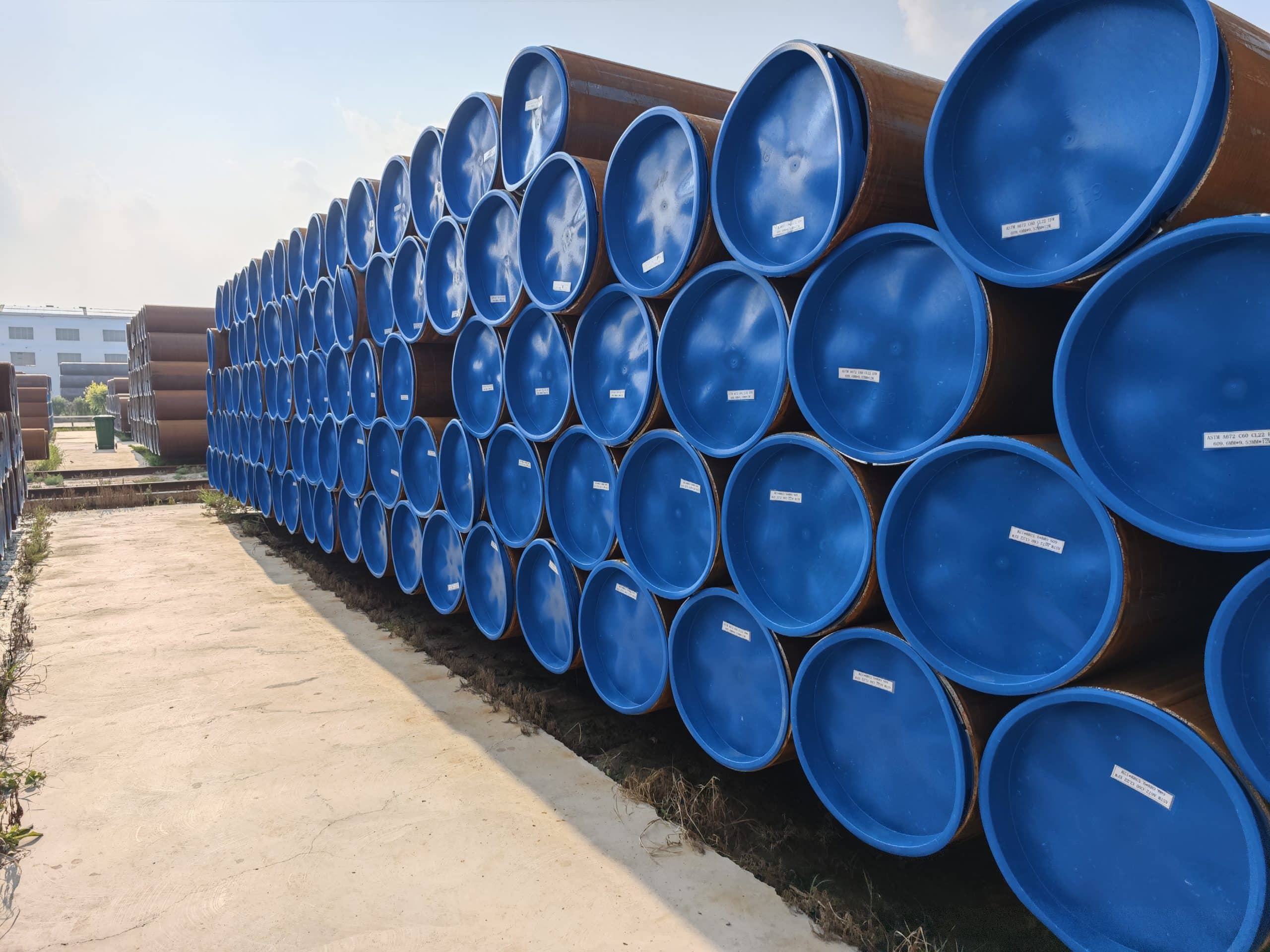
- 1. Why Does Anti-Corrosion Coating Directly Determine Pipeline Service Life?
- 2. Six Common Anti-Corrosion Coating Types: Quick Reference
- 3. Seven Coating Defect Types Fully Explained: Identification, Root Causes, and Risk Rating
- 4. Three Root Causes of Anti-Corrosion Coating Defects
- 5. Four Anti-Corrosion Inspection Methods: Execution Steps and Standards
- 6. Coating Defect Repair Decision Matrix
- 7. LONGMA In-House Laboratory: Full-Process Anti-Corrosion Quality Control
- 8. Anti-Corrosion Pipe Supplier Evaluation Checklist
- 9. FAQ: Steel Pipe Anti-Corrosion Coating — Common Procurement Questions
- 10. About LONGMA: Steel Pipe Supplier with Comprehensive Anti-Corrosion Quality Control
Applications: Oil & Gas · Municipal Water Supply · Petrochemical Plants · Power Engineering · Offshore Engineering · Long-Distance Pipelines
Industry data shows that more than 60% of global steel pipe failures are corrosion-related — and a significant proportion of those failures originate in anti-corrosion coating defects. A pinhole smaller than 1 mm is enough to initiate severe localized corrosion and cause premature pipeline failure. High-quality anti-corrosion coating extends steel pipe service life to 30–50 years and substantially reduces whole-life maintenance costs.
This guide provides a systematic breakdown of 7 common coating defect types with root-cause analysis, 4 NDT inspection methods with execution steps, a repair decision matrix, and a supplier evaluation checklist — giving buyers a complete framework for assessing anti-corrosion coating quality.
Why Does Anti-Corrosion Coating Directly Determine Pipeline Service Life?
Steel pipe operates for decades in wet, buried, marine, high-temperature, or chemically aggressive environments. Once the coating fails, the following failure chain is set in motion:
| Failure Mode | Trigger Condition | Impact on Pipeline |
| External wall corrosion / pitting | Coating damage; Holiday defects | Wall thinning; reduced pressure-bearing capacity |
| Stress corrosion cracking (SCC) | High stress + corrosive medium acting together | Sudden brittle fracture; extremely severe consequence |
| Coating disbondment / blistering | Insufficient adhesion; incomplete curing | Large unprotected area; accelerated corrosion propagation |
| Cathodic disbondment | Excessively negative CP potential + poor coating quality | Corrosion accelerates in the zone where cathodic protection has failed |
| Transmitted medium leakage | Corrosion perforation through pipe wall | Shutdown; environmental incident; major financial loss |
Six Common Anti-Corrosion Coating Types: Quick Reference
Different service environments require different coating systems. The following table covers the six coating types most commonly specified on international pipeline projects:
| Coating Type | Key Characteristics | Typical Application | Key Standard |
| 3PE (Three-Layer Polyethylene) | Excellent mechanical damage resistance; best overall performance; most widely used globally | Buried long-distance pipelines (oil, gas, water) | DIN 30670 / ISO 21809-1 |
| FBE (Fusion-Bonded Epoxy) | Good bond to concrete; used for both internal and external coating | Bends, field joints, internal lining, water pipe | CSA Z245.20 / ISO 21809-2 |
| Dual-Layer FBE (DL-FBE) | Primer + adhesive layer integrated; superior cathodic disbondment resistance | High-corrosivity soils; subsea pipelines | CSA Z245.20 |
| Coal Tar Epoxy | Low cost; good water resistance; suited for non-critical applications | General buried pipe; tank bottoms | SY/T 0447 |
| Polyurethane Insulation Coating | Combines corrosion protection and thermal insulation | Road/river crossings; insulated oil transmission pipe | ISO 21809-3 |
| Liquid Epoxy (Internal Lining) | Smooth bore surface; reduces flow resistance; prevents internal corrosion | Natural gas pipe interior; potable water pipe | ISO 15741 |
Seven Coating Defect Types Fully Explained: Identification, Root Causes, and Risk Rating
Based on ISO 21809 and applicable ASTM standards, anti-corrosion coating defects fall into the following seven categories — each with a distinct risk rating and repair strategy:
Defect 1: Holiday (Coating Void) — Risk Rating ★★★★★
| Dimension | Details |
| Root Causes | Missed spray coverage; surface contaminant causing coating rupture; mechanical damage during handling |
| Visual Characteristics | Typically invisible to the naked eye; detected by spark testing only |
| Impact on Pipeline | A void smaller than 1 mm creates a localized galvanic cell, initiating pitting corrosion and perforation |
| Detection Method | Holiday Test (spark test) — ASTM G62 / ISO 21809-3 |
| Repair Method | Epoxy repair stick or liquid epoxy patch coat; re-test after curing |
Defect 2: Blister — Risk Rating ★★★★★
| Dimension | Details |
| Root Causes | Moisture or salt contamination on pipe surface; excessive application temperature; incomplete curing |
| Visual Characteristics | Coating surface raised in domes of varying size |
| Impact on Pipeline | When blisters rupture, the steel substrate is exposed; adhesion fails and corrosion spreads rapidly |
| Detection Method | Visual Testing (VT) + Pull-Off Adhesion Test |
| Repair Method | Grind back to bare metal; clean and dry; reapply coating |
Defect 3: Disbondment — Risk Rating ★★★★★
| Dimension | Details |
| Root Causes | Surface preparation below Sa2½; incomplete curing; primer did not adequately wet the substrate |
| Visual Characteristics | Coating separates from the pipe substrate; can be peeled away |
| Impact on Pipeline | Loss of corrosion protection over a large area; accelerates general corrosion across the entire zone |
| Detection Method | Pull-Off Adhesion Test (ASTM D4541) + Cathodic Disbondment Test |
| Repair Method | Remove all disbonded material; re-blast to Sa2½; apply new coating |
Defect 4: Crack — Risk Rating ★★★★★
| Dimension | Details |
| Root Causes | Excessive thermal stress (abnormal curing temperature); coating too thick; low-temperature application embrittlement |
| Visual Characteristics | Linear cracking visible on coating surface or in cross-section |
| Impact on Pipeline | Crack propagation exposes the steel substrate; corrosive media make direct contact with the pipe wall |
| Detection Method | Visual Testing (VT) + Holiday Test |
| Repair Method | Localized cracks: cut out and patch coat. Extensive cracking: return to factory for full recoating |
Defect 5: Pinhole — Risk Rating ★★★★★
| Dimension | Details |
| Root Causes | Excessive spray speed; viscosity too high; coating thickness insufficient |
| Visual Characteristics | Dense pattern of tiny needle-like holes across the coating surface |
| Impact on Pipeline | Creates multiple simultaneous corrosion initiation sites; accelerates wall thinning |
| Detection Method | Holiday Test (spark test) |
| Repair Method | Apply additional coat to reach specified minimum thickness; re-test after drying and curing |
Defect 6: Non-Uniform Thickness — Risk Rating ★★★★☆
| Dimension | Details |
| Root Causes | Spray equipment parameter deviation; unstable operator technique; uneven pipe rotation speed |
| Visual Characteristics | Under-thickness areas may appear semi-transparent |
| Impact on Pipeline | Thin zones have reduced impact resistance; susceptible to stone damage after backfill |
| Detection Method | Magnetic thickness gauge multi-point measurement (ASTM D7091 / ISO 19840) |
| Repair Method | Apply additional coat in under-thickness zones to reach specified thickness range |
Defect 7: Sagging — Risk Rating ★★★☆☆
| Dimension | Details |
| Root Causes | Coating applied too thick; application environment temperature too low; curing speed too slow |
| Visual Characteristics | Coating drips or runs, forming teardrop-shaped streaks or uneven surface |
| Impact on Pipeline | Affects appearance and thickness uniformity; severe sagging can lead to coating cracking |
| Detection Method | Visual Inspection + thickness gauge verification |
| Repair Method | Grind sagging area flat; apply additional coat to restore uniform thickness |
Three Root Causes of Anti-Corrosion Coating Defects
4.1 Inadequate Surface Preparation
The most common root cause of coating failure. ISO 8501-1 requires a blast cleaning grade of Sa2½, with surface roughness of 40–100 μm. Any of the following surface conditions will reduce adhesion:
| Surface Defect | Standard Requirement | Impact on Coating |
| Mill scale residue | Removal rate ≥ 95% (Sa2½) | Blocks bonding between coating and substrate |
| Oil / salt contamination | ISO 8502-9: salt content ≤ 20 mg/m² | Causes blistering and disbondment |
| Dust | ISO 8502-3: dust rating ≤ 2 | Creates embedded inclusions within the coating layer |
| Insufficient roughness | Target Rz: 40–100 μm | Poor anchor profile; low adhesion strength |
4.2 Coating Thickness Out of Control
Both under-thickness and over-thickness produce defects — but in different failure directions:
| Coating Type | Standard Thickness Range | Too Thin: Risk | Too Thick: Risk |
| FBE | 300–500 μm | Susceptible to perforation; poor impact resistance | Non-uniform curing; internal stress cracking |
| 3PE Outer PE Layer | 2.0–4.5 mm (diameter-dependent) | Reduced mechanical damage resistance | High thermal shrinkage stress; prone to cracking |
| Liquid Epoxy Internal Lining | 50–200 μm | Reduced abrasion resistance | Sagging; incomplete curing |
4.3 Abnormal Curing Temperature
FBE is a thermosetting material — the curing temperature directly determines the final coating performance. Modern production lines should be equipped with PLC closed-loop temperature control:
| Temperature Deviation | Effect on Coating | Control Measure |
| Too low (incomplete cure) | Reduced adhesion; poor chemical resistance; increased blister risk | Infrared thermometry + automatic temperature compensation |
| Too high (over-cure) | Resin degradation; reduced flexibility; brittle fracture in cold service | PLC upper temperature limit alarm and shutdown protection |
| Unstable / fluctuating | Non-uniform coating properties; high scatter in local performance | Full-line temperature sensor with real-time recording |
Four Anti-Corrosion Inspection Methods: Execution Steps and Standards
Coating quality must be verified through systematic inspection — visual judgment alone is insufficient. The following four methods cover all critical quality dimensions:
| Inspection Method | Purpose | Execution Summary | Key Standards |
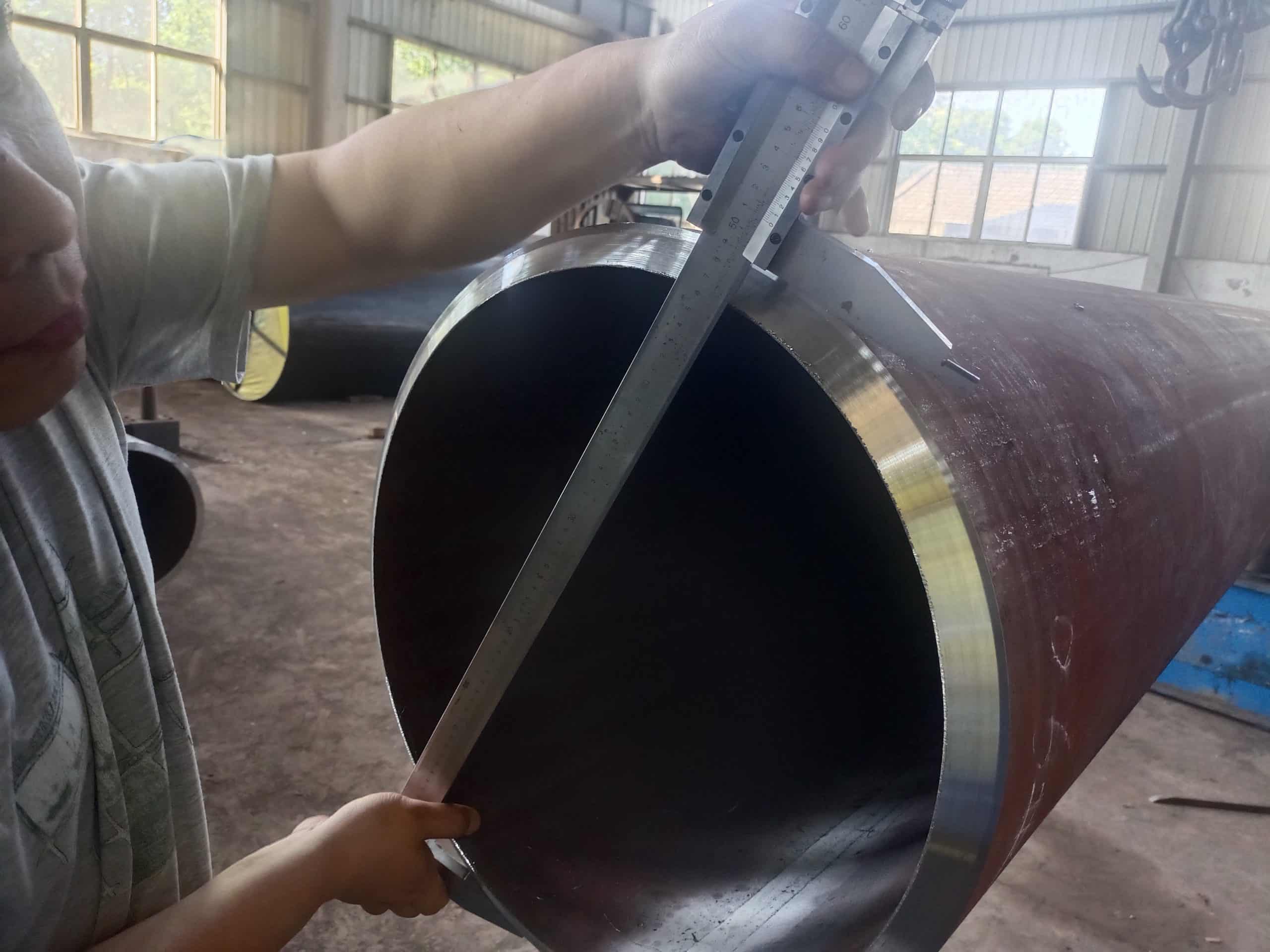
| Coating Thickness Measurement | Confirm anti-corrosion layer meets design thickness | Clean inspection zone → magnetic gauge multi-point measurement (≥ 5 points/pipe) → record max / min / average values | ASTM D7091 / ISO 19840 |
| Holiday Test (Spark Test) | Detect pinholes and voids invisible to the naked eye | Connect HV power → electrode scans 100% of pipe surface → mark spark locations as holidays → repair and re-test | ASTM G62 / ISO 21809-3 |
| Pull-Off Adhesion Test | Verify bond strength between coating and steel substrate | Bond test dolly → hydraulic pull-off → record failure load and failure mode → evaluate against acceptance criterion | ASTM D4541 / ISO 4624 |
| Impact Resistance Test | Verify coating withstands transportation and construction impact | Drop weight at specified energy onto pipe sample → Holiday Test at impact point → pass if no holidays detected | ASTM G14 / ISO 21809 |
⚠️ The Holiday Test is the most critical anti-corrosion inspection in the oil and gas industry. It must be performed on 100% of every pipe — spot-checking is not an acceptable substitute. Any repaired holiday must be re-tested before the pipe is accepted.
Coating Defect Repair Decision Matrix
The appropriate repair strategy depends on defect type, affected area, and severity. The matrix below can be used directly for on-site disposition decisions:
| Defect Type | Area / Severity | Repair Method | Field Repair? | Post-Repair Mandatory Inspection |
| Holiday | Single point / scattered | Epoxy repair stick or liquid epoxy patch | ✓ Yes | Holiday Test re-inspection |
| Blister | Localized (< 5%) | Grind to bare metal + reapply coating | ✓ Yes | Thickness + Holiday Test |
| Blister | Extensive (> 20%) | Return to factory for full recoating | ✗ Return to factory | Full acceptance test suite |
| Disbondment | Localized | Remove disbonded area + patch coat | ✓ Yes | Adhesion + Holiday Test |
| Disbondment | Extensive | Return to factory for full recoating | ✗ Return to factory | Full acceptance test suite |
| Crack | Fine surface cracks | Cut out affected zone + patch coat | ✓ Situation-dependent | Holiday Test re-inspection |
| Crack | Through-thickness cracks | Return to factory for full recoating | ✗ Return to factory | Full acceptance test suite |
| Under-thickness | Localized | Additional coat to reach specified thickness | ✓ Yes | Thickness + Holiday Test |
| Sagging | Localized | Grind flat + apply additional coat | ✓ Yes | Thickness inspection |
LONGMA In-House Laboratory: Full-Process Anti-Corrosion Quality Control
For major international projects, final-product sampling is nowhere near sufficient. LONGMA has established a complete anti-corrosion quality control system covering every stage from incoming raw material through finished product shipment:
| Inspection Stage | Items Inspected | Purpose |
| Incoming Raw Material | Chemical composition / mechanical properties / salt content / surface roughness | Verify pipe substrate quality and blast cleaning effectiveness |
| In-Process Coating Application | Curing temperature (PLC recorded) / in-line thickness monitoring / spray speed | Detect and correct process deviations in real time |
| Finished Product — Full Scope | Holiday Test / adhesion / impact resistance / cathodic disbondment / salt spray corrosion / bend performance | Comprehensive verification of finished coating quality |
| Document Archiving | Coating process records / inspection reports / EN 10204 3.1 MTC | Supports third-party acceptance and export customs clearance |
LONGMA supplies 3PE, FBE, dual-layer FBE, and polyurethane insulation coating across multiple coating types. Third-party witnessing by SGS, BV, TÜV, and DNV is supported. Coating inspection reports are fully cross-referenced to pipe heat numbers and MTC documents.
Anti-Corrosion Pipe Supplier Evaluation Checklist
The evaluation dimensions below can be used directly for RFQ drafting and supplier qualification assessment:
| Evaluation Item | Recommended Requirement | How to Verify |
| Coating standard compliance | ISO 21809 / DIN 30670 / CSA Z245.20 | Request certification documents and historical inspection reports |
| Surface preparation capability | Sa2½ blast cleaning; Rz 40–100 μm | Request roughness gauge calibration records |
| Thickness control | In-line measurement system; ≥ 5 points per pipe | Review inspection records and equipment list |
| Holiday Test capability | 100% full-pipe scan; voltage set per coating thickness | Request test equipment documentation and historical reports |
| Adhesion test results | ≥ 10 MPa (FBE) / ≥ 14 MPa (3PE intermediate layer) | Request Pull-Off Test data |
| Cathodic disbondment test | 28 days / 65°C (DL-FBE standard) | Request test report |
| Third-party inspection | SGS / BV / TÜV / DNV | Name inspection body and hold points in PO |
| MTC traceability | EN 10204 3.1; heat number cross-referenced to coating records | Request sample MTC for verification |
FAQ: Steel Pipe Anti-Corrosion Coating — Common Procurement Questions
Q1: Which is better for buried oil and gas pipelines — 3PE or FBE?
They serve different roles and are not interchangeable. 3PE is the first choice for buried oil and gas transmission mainlines: its three-layer structure (FBE primer + adhesive + PE outer layer) combines excellent adhesion and mechanical protection, delivering the best overall performance. FBE is used for field joints, bends, and internal lining — and also serves as the primer layer within the 3PE system. For high-corrosivity soils or subsea pipelines, dual-layer FBE (DL-FBE) is the superior option due to its better cathodic disbondment resistance.
Q2: How is the Holiday Test voltage determined?
The test voltage must be calculated based on coating thickness according to the applicable standard. Common reference values: FBE (300–500 μm) — approximately 1,500–2,500 V; 3PE (2.0–4.5 mm) — approximately 10,000–25,000 V. The exact value should be determined using the calculation formula in ASTM G62 or ISO 21809-3, and the actual voltage used must be recorded in the inspection report.
Q3: What precautions are needed when transporting coated steel pipe?
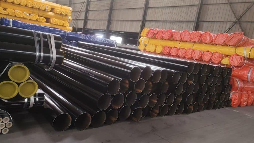
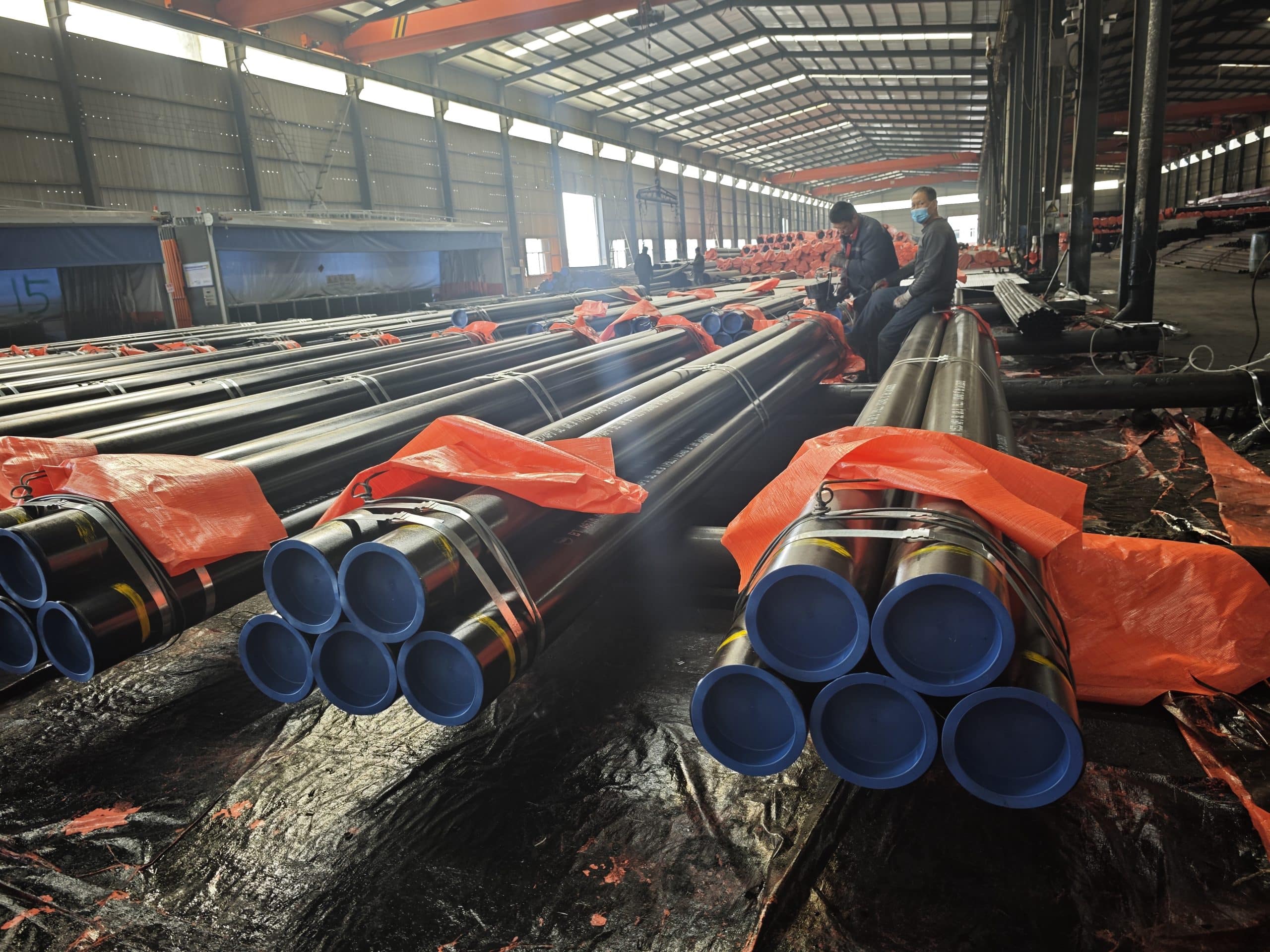
The most common transport damage to anti-corrosion coatings comes from pipe-end impact and pipe-body rolling friction. Recommended measures: install plastic end caps on pipe ends; separate pipes with rubber or timber padding between layers; apply strapping at controlled tension — over-tightening compresses the coating; upon delivery, inspect pipe ends and body for coating scratches, and conduct a Holiday Test re-check immediately on any suspected damage areas.
Q4: What does the Cathodic Disbondment Test measure?
The Cathodic Disbondment (CD) test simulates the tendency of a coating to separate from the pipe substrate under the influence of a cathodic protection system. The standard test is typically conducted at 65°C for 28 days (per the DL-FBE specification), measuring the disbondment radius from the test holiday. A smaller disbondment radius indicates better resistance to cathodic disbondment — and greater suitability for long-term buried service alongside a cathodic protection system.
Q5: How can I verify a supplier’s anti-corrosion quality at the procurement stage?
Verify from the following angles: ① Request historical Holiday Test reports and Pull-Off adhesion test data; ② Review FBE / 3PE curing temperature records (PLC-generated records are more credible than manual logs); ③ Confirm blast cleaning grade and roughness measurement records; ④ Request Cathodic Disbondment test reports (mandatory for DL-FBE); ⑤ Arrange on-site witnessing of the coating process by SGS, BV, or TÜV — this is the most direct and reliable verification method available.
About LONGMA: Steel Pipe Supplier with Comprehensive Anti-Corrosion Quality Control
LONGMA has over 20 years of experience in steel pipe manufacturing, with anti-corrosion services covering 3PE, FBE, dual-layer FBE, and polyurethane insulation coating:
▸ Coating standards: ISO 21809 / DIN 30670 / CSA Z245.20 / SY/T 0413 — full system coverage
▸ Blast cleaning: Sa2½ grade; roughness Rz 40–100 μm; salt content compliant with ISO 8502-9
▸ 100% Holiday Test + full-pipe thickness measurement + adhesion / cathodic disbondment testing
▸ PLC automatic temperature control with full curing temperature recording; coating process parameters fully traceable
▸ EN 10204 3.1 MTC with coating inspection reports cross-referenced to pipe heat numbers throughout
▸ Third-party inspection support: SGS / BV / TÜV / DNV — in-process witnessing and pre-shipment inspection available
▸ Field joint coating materials available; customized transport packaging solutions
If you are sourcing 3PE coated steel pipe, FBE-coated pipe, or have anti-corrosion quality questions, contact LONGMA for: coating type selection guidance · sample inspection reports · coating process documentation · project quotation.